
Ever wonder what the deal is with that pesky “EMISS MAINT” light and what that funky timer under the dash is all about? Well hang tight and we’ll find out!
TL;DR:
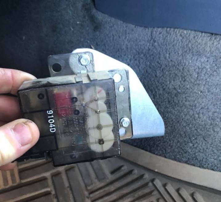
There is a small timer near the steering column that turns on the Emissions light at 82k miles. Replace your o2 sensor and chuck the timer as it’s not important or ressetable*(See Later).
Intro
If you’ve dug around in a Renix equipped Jeep for any amount of time, you’ve probably had a really hard time finding a Check Engine Light or OBD2 port. Well that’s because the Renix era was in the land before gov mandated On-Board Diagnostics and each manufacturer only added whatever funky mess they felt was necessary.
Renix Equipped Jeeps do have a diagnostic port under the hood, but it’s very rare to find an affordable commercial scan tool that will interface with it (see: REM). There is also a yellow warning light on the dash that may look like a CEL at first glance, but it’s sadly much simpler than that. Today’s topic will be all about the Emissions Maintenance Light and how it works.
Purpose
An excerpt from the 1990 Jeep FSM states: “The emission maintenance timer and indicator light are used to alert the owner when oxygen sensor-PCV valve replacement and other scheduled emission maintenance is required.” Basically when the light goes off, it’s time to change the o2 Sensor and PCV Valve to keep up with the emissions service interval. The only issues is this is a one time deal and once the light goes off, the timer is considered spent and can’t be serviced. We’ll see about that.
The FSM continues with: “The timer is operated by the ignition system. It activates .. when vehicle mileage reaches the scheduled maintenance interval of approximately 133,000 kilometers (82,500 miles).” The slightly misleading part here is about the mileage however, since it’s only an approximation. Renix uses a mechanical speedometer cable that the timer doesn’t even interface with. Instead, the timer is actually just an hour counter connected to ignition which goes off after 2,750 Hours. Not the best way to determine sensor failure, but a simple reminder is better than nothing I suppose.
Tear Down
My timer was already spent when I got my Jeep, so it was removed and that was the end of that. These units are NOT built to be opened as the 3 snap tabs that hold the clam shell together are all glued in place. Glue was not heat activated, but 340°F of hot air helped soften the plastic enough to sort of warp and chisel through. Once inside you’ll find a circuit board and maze of gears that make up the core.

A tensioned wire acts as our switch mechanism and when triggered will provide a path to ground and illuminate the dash light. This wire contact rides on a ridge of the lowest gear which has a ramp at the end. When the last gear is finally able to make a full rotation, that ramp kicks the contact off, allowing it to connect to the nearby ground pin.

Circuit Board
The circuit board is actually a fairly smart counter with a little digital IC setup. The main IC is a Motorola MC14060BCP which is a 14-Bit Binary Counter and Oscillator and uses a crystal to keep track of time pulses. This is paired with the other IC, a Motorola MC14027BCP, which is a Dual J-K Flip Flop. From the sounds of it, the 60 keeps count and sends a pulse to the 27 which will control the state of the coil and turn the motor in increments.
Nearly everything else is just basic power filtering so nothing overly fancy here. Looks like the only things you could play with are MAYBE R2 or C3 but I’m not entirely sure how they would play with the clock. Didn’t feel like learning the data sheet enough to really find out.

Resetting
If after all that, you are still interested in resetting the device for another go then you’ve got a few options. Opening the device as intended is quite difficult and there is a good chance nearly all the tabs will be broken in the process. You could just cut them anyway to get in and then find some other way to hold it together, but there also appears to be an access hole behind the rear sticker so you can get to the important bits. Since the timer doesn’t know when it has tripped, it will spin forever, so all you need to do is pop the metal contact back onto the lower gear and you’re good for another go.
Other Notes
Interesting fun fact: the notch flicker gear has numbers 0-9 printed around the outside so you could probably see the time left on the timer from the back. The last few stages switch from a traditional gear tooth to some sort of incrementing style. They only have 1 notch on the whole gear that will nudge a smaller gear so each full rotation will only make a single push rather than a slow continuous spin. I guess that is used to get more of a ticking action instead of a constant slow rotation.
The drive gear moves in a ticking fashion due to the simple design. Each tick is approx 1 second and rotates the drive gear a 1/4 turn. That’s roughly a 2.5 Million : 1 reduction ratio!
does the signal come from the ECU to rotate the gears… also would it be possibal to take the signal and run it straight to the light and get the light to work correctly
The timer is self contained and just runs off the ignition circuit.
I believe all you need to do is jump the light pin with 12v or gnd on the timer connector to make the dash light turn on.